How do I use Digital I/O pins in Multi-instrument Mode

Written by Heyang Long
Updated at January 10th, 2024
Moku:Go features 16 bi-directional pins, providing users the flexibility to utilize them either as 16 individual standalone signal pins or to combine them into a single int16 line. This Knowledge Base article will explain how to use Digital I/O pins in Multi-instrument Mode on Moku:Go.
1. Standalone digital pins
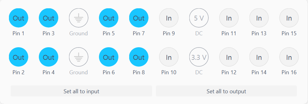
Each of the 16 pins on Moku:Go can be set as a digital output pin individually, and can be controlled by the integrated pattern generator in Logic Analyzer. Pins 1~8 were configured as output pins and Pins 9~16 were configured as input pins. Pins 1~8 were looped back to Pins 9~16 externally with jump wires.
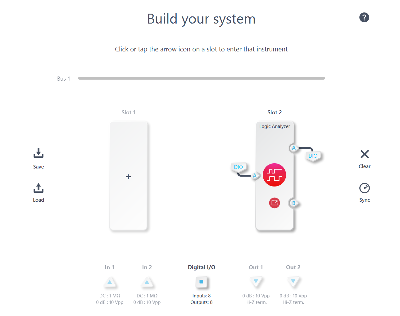
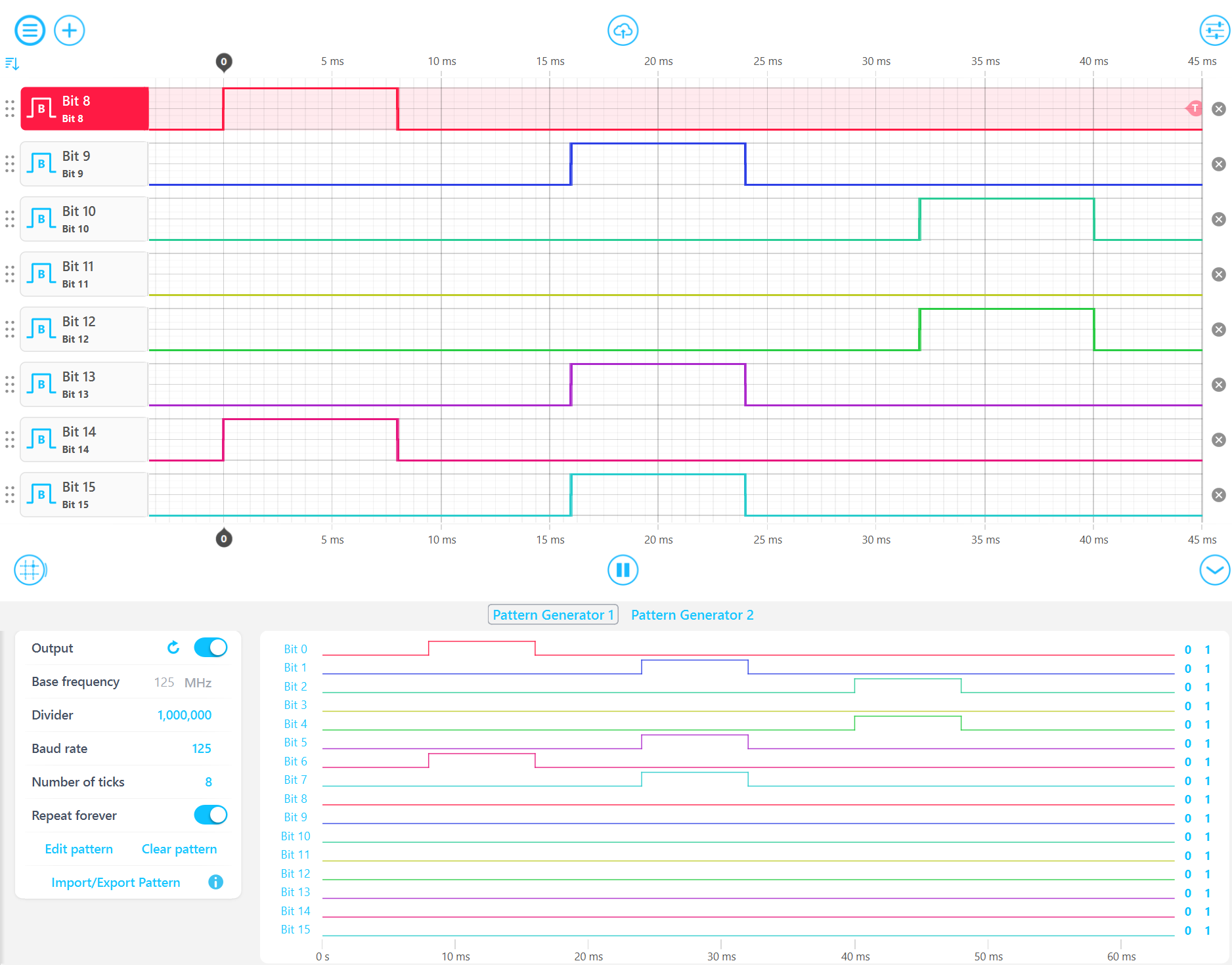
In this setup, the Logic Analyzer/Pattern Generator can both read signals from certain digital pins and output signals to other digital pins concurrently. As illustrated in the figure below, the Logic Analyzer accurately captures the signal generated by Pattern Generator 1 through DIO and jump wires. Please note that the Bits are 0-based while Pins are 1-based.
2. Combined as an int16 signal
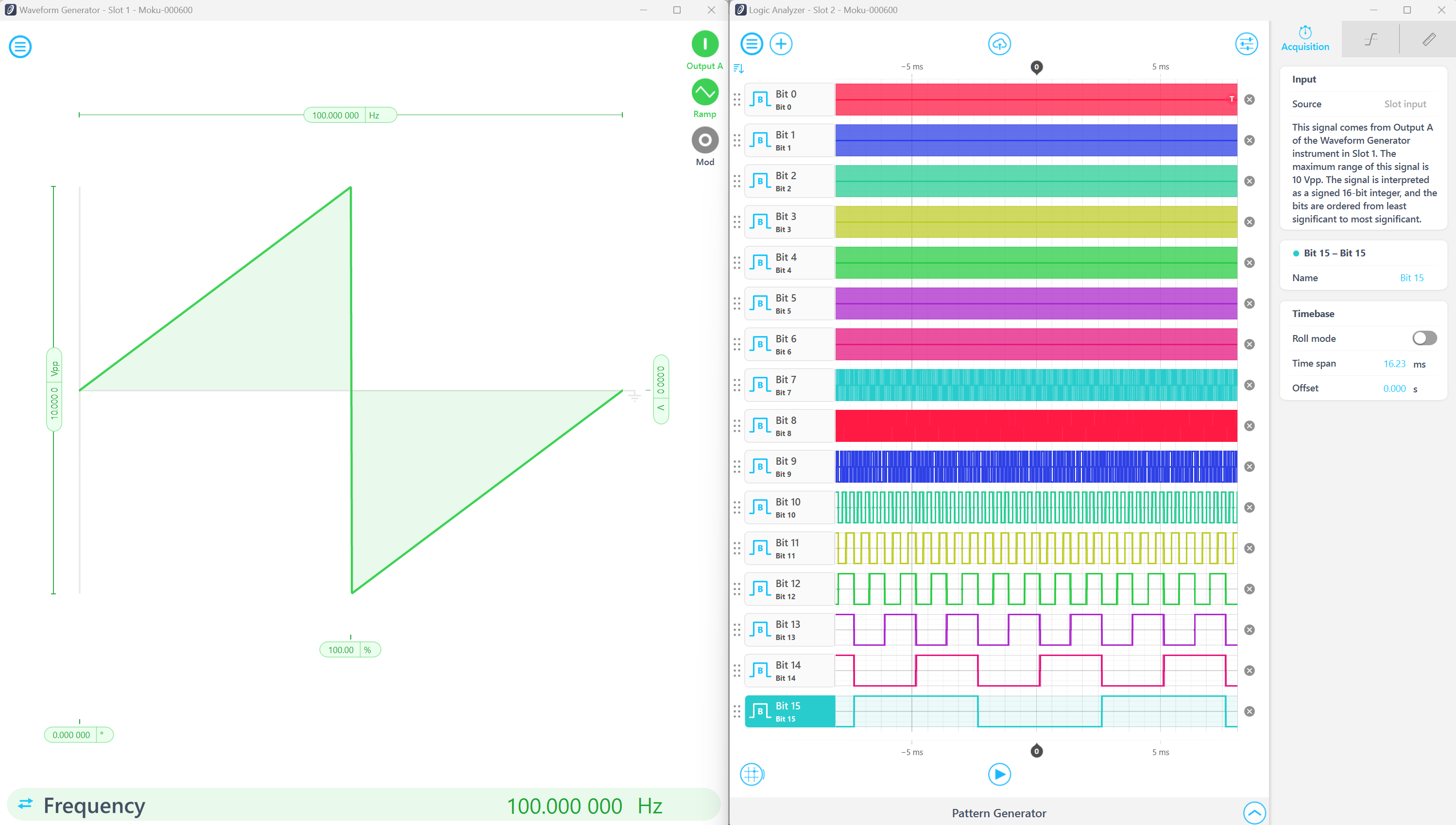
The digital pins can be mapped to an int16 signal line, ranking from the least significant bit (LSB) to the most significant bit (MSB). For instance, Pin 1 corresponds to Bit 0 (LSB) in the int16 signal line, while Pin 16 aligns with Bit 15 (MSB) in the same line. In the depicted configuration shown in the screenshot below, the Waveform Generator produces a 16-bit ramp wave through the DIO; and simultaneously, Logic Analyzer visualizes the output waveforms on the 16 pins.
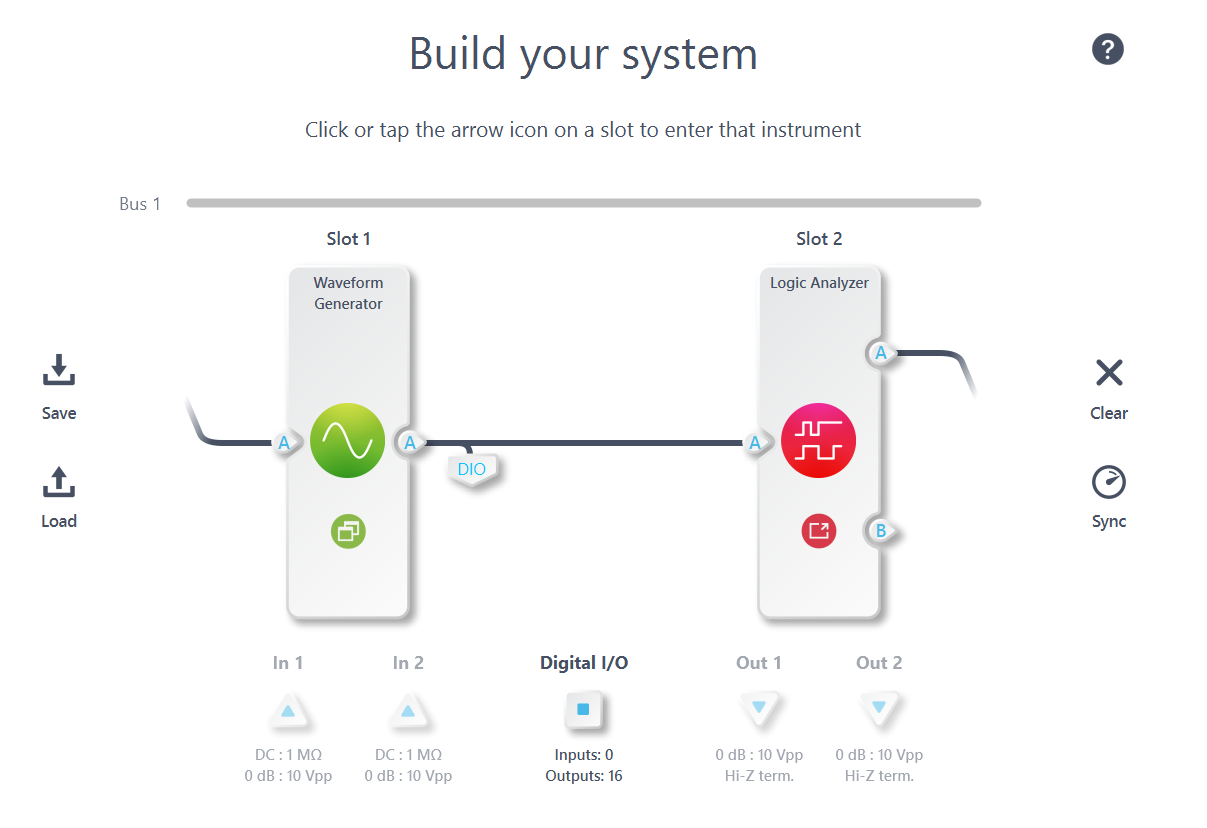
The ramp waveform is set as 100 Hz repetition rate and 10 Vpp amplitude. Waveforms on Logic Analyzer indicate that the higher-order bits experience fewer transitions, whereas the lower-order bits exhibit more transitions. This observation aligns with the anticipated behavior since the most significant bit (MSB) changes only twice within each cycle, while the least significant bit (LSB) changes with nearly every update of the waveform.
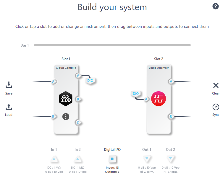
3. Moku Cloud Compile
Through MCC, there's a broader scope for creating adaptable and tailored algorithms using DIO. You have the capability to craft your digital signal generator and transmit the signal through DIO. For instance, consider this MCC program: it reads a trigger signal from Pin 1 and generates three digital triggers on Pins 5 through 7. Subsequently, Pins 5 through 7 are looped back to Pins 2 through 4 and can be observed using the Logic Analyzer.
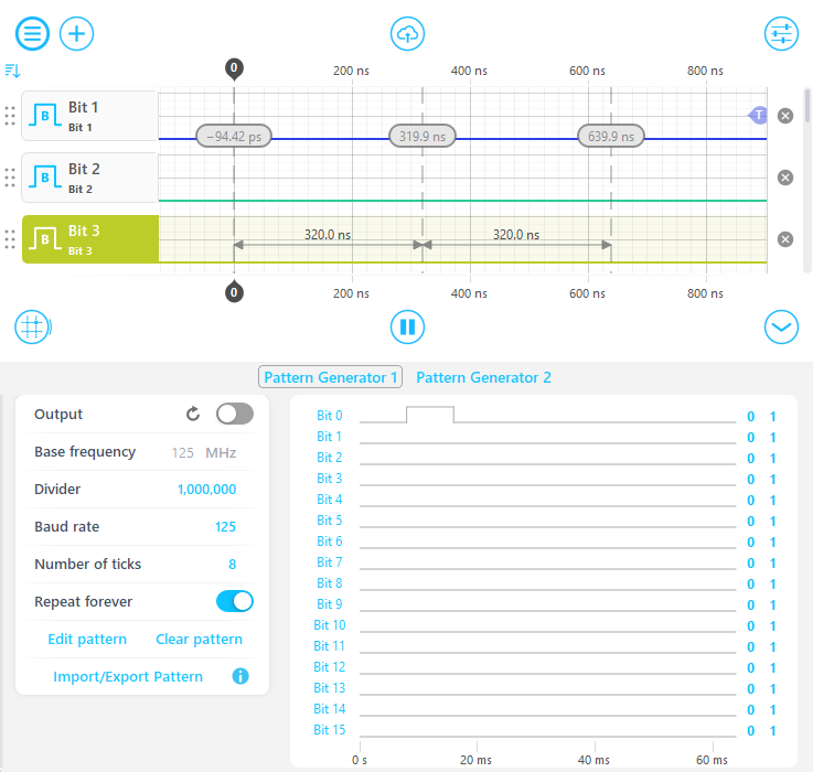
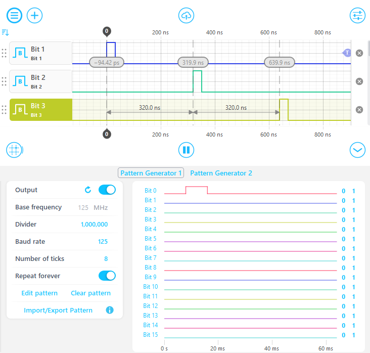
For example, the attached MCC program generates three trigger signals with a 10-clock-cycle gap between each adjacent trigger upon receiving an input trigger signal. The following figure displays both non-triggered (left) and triggered (right) output results. The 320 ns (10 * 1/31.25 MHz) delay between the trigger signals is observable in the triggered figure.
The VHDL code for generating MCC bitstreams is provided below. To generate the bitstream, please follow this link: Moku Cloud Compile - A getting started guide
LIBRARY IEEE;
USE IEEE.std_logic_1164.ALL;
USE IEEE.numeric_std.ALL;

ENTITY SystemSync IS
  PORT( clk                 : in std_logic;
        triggerIn           : in std_logic;
        triggerOut0         : out std_logic;
        triggerOut1         : out std_logic;
        triggerOut2         : out std_logic
        );
END SystemSync;

ARCHITECTURE rtl OF SystemSync IS
  type t_state is (Waiting, Running);
  signal State : t_state := Waiting;

  signal prevTriggerIn : std_logic;
  signal count : unsigned(15 downto 0);

  begin

    process(clk) is
    begin
      if rising_edge(Clk) then
        prevTriggerIn <= triggerIn;

      case State is
        when Waiting =>
        if(prevTriggerIn /= '1' and triggerIn = '1') then
          State <= Running;
        else
          State <= State;
        end if;

        when Running =>
        if(count /= to_unsigned(31,count'length)) then
          count <= count + to_unsigned(1,count'length);
          State <= State;
        else
          count <= to_unsigned(0,count'length);
          State <= Waiting;
        end if;

        if (count = to_unsigned(10,count'length)) then
           triggerOut0 <= '1';
           triggerOut1 <= '0';
           triggerOut2 <= '0';
        elsif (count = to_unsigned(20,count'length)) then
           triggerOut0 <= '0';
           triggerOut1 <= '1';
           triggerOut2 <= '0';
        elsif (count = to_unsigned(30,count'length)) then
           triggerOut0 <= '0';
           triggerOut1 <= '0';
           triggerOut2 <= '1';
        else
           triggerOut0 <= '0';
           triggerOut1 <= '0';
           triggerOut2 <= '0';
        end if;
      end case;
     end if;
    end process;

  end rtl;


library IEEE;
use IEEE.Std_Logic_1164.All;
use IEEE.Numeric_Std.all;

architecture TopWrapper of CustomWrapper is

begin
  U_sync:ENTITY WORK.SystemSync
  PORT map( clk                 => clk,
        triggerIn               => InputA(0),
        triggerOut0             => OutputA(5),
        triggerOut1             => OutputA(6),
        triggerOut2             => OutputA(7)
        );

END architecture;