What is the Rect-to-Polar conversion range?
How to select the conversion range to optimise signal detection in Lock-in Amplifier

Written by Nandi Wu
Updated at June 9th, 2023
-
Moku:Go
Moku:Go General Moku:Go Arbitrary Waveform Generator Moku:Go Data Logger Moku:Go Digital Filter Box Moku:Go FIR Filter Builder Moku:Go Frequency Response Analyzer Moku:Go Logic Analyzer & Pattern Generator Moku:Go Oscilloscope & Voltmeter Moku:Go PID Controller Moku:Go Spectrum Analyzer Moku:Go Waveform Generator Moku:Go Power Supplies Moku:Go Lock-in Amplifier Moku:Go Time & Frequency Analyzer Moku:Go Laser Lock Box Moku:Go Phasemeter
-
Moku:Lab
Moku:Lab General Moku:Lab Arbitrary Waveform Generator Moku:Lab Data Logger Moku:Lab Digital Filter Box Moku:Lab FIR Filter Builder Moku:Lab Frequency Response Analyzer Moku:Lab Laser Lock Box Moku:Lab Lock-in Amplifier Moku:Lab Oscilloscope Moku:Lab Phasemeter Moku:Lab PID Controller Moku:Lab Spectrum Analyzer Moku:Lab Time & Frequency Analyzer Moku:Lab Waveform Generator Moku:Lab Logic Analyzer/Pattern Generator
-
Moku:Pro
Moku:Pro General Moku:Pro Arbitrary Waveform Generator Moku:Pro Data Logger Moku:Pro Frequency Response Analyzer Moku:Pro Oscilloscope Moku:Pro PID Controller Moku:Pro Spectrum Analyzer Moku:Pro Waveform Generator Moku:Pro Lock-in Amplifier Moku:Pro Laser Lock Box Moku:Pro Digital Filter Box Moku:Pro FIR Filter Builder Moku:Pro Phasemeter Moku:Pro Multi-instrument Mode Moku:Pro Logic Analyzer/Pattern Generator Moku:Pro Time & Frequency Analyzer
- Python API
- MATLAB API
- Arbitrary Waveform Generator
- Data Logger
- Digital Filter Box
- FIR Filter Builder
- Frequency Response Analyzer
- Laser Lock Box
- Lock-in Amplifier
- Oscilloscope
- Phasemeter
- PID Controller
- Spectrum Analyzer
- Time & Frequency Analyzer
- Waveform Generator
- Logic Analyzer & Pattern Generator
- Multi Instrument Mode
- Moku Cloud Compile
- Moku general
- LabVIEW
- mokucli
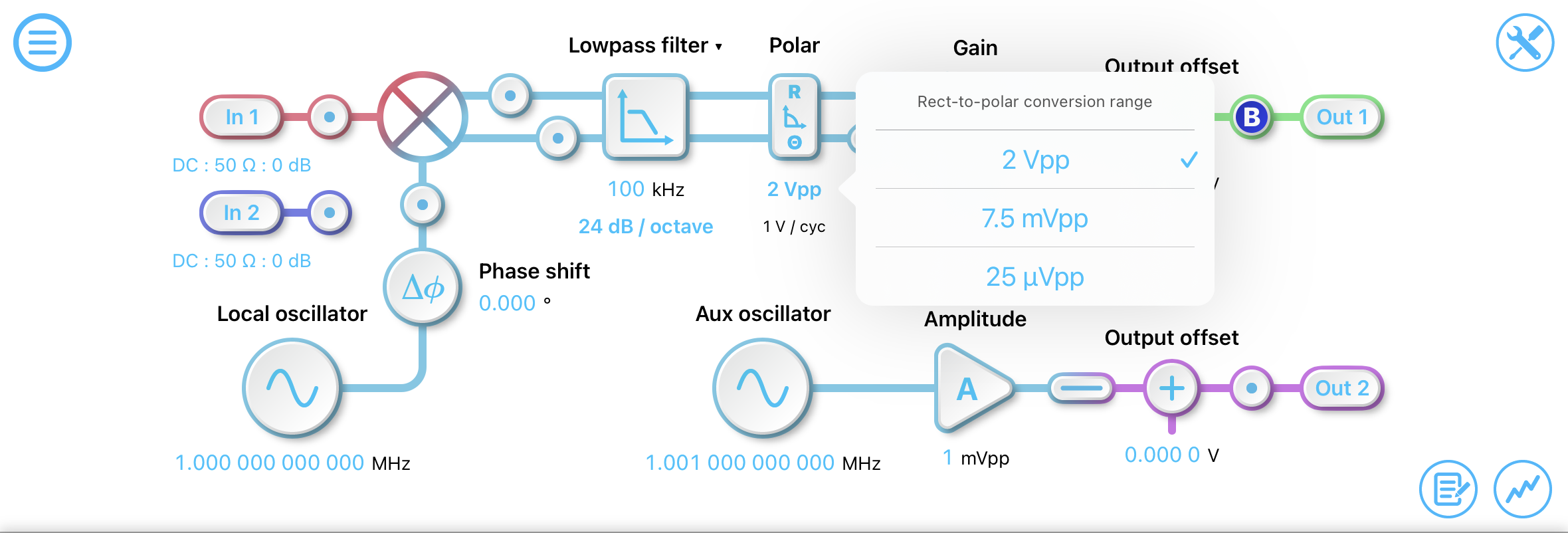
What is the Rect-to-Polar conversion range?
When using the Lock-in Amplifier in Polar mode, there is a “2 Vpp” parameter below the R/Theta box. This is where you can select the rect-to-polar conversion range of the Lock-in Amplifier. This conversion range sets the largest signal amplitude that can be detected by the Lock-in Amplifier.
What conversion range should I use?
We recommend selecting the smallest range that can fit your signal of interest.
For example, if the signal of interest is 1 mVpp, the recommend conversion range to use is 7.5mVpp; if the signal of interest is 10 mVpp, this is above the 7.5 mVpp range and therefore the 2 Vpp range should be used. If in doubt, start with the 2 Vpp conversion range.
Note that this is not the amplitude of the input signal into Input 1, as the noise at the frontend can be higher than the signal of interest in the Lock-in Amplifier.
What does it look like if I'm not using the optimal conversion range
If you are unsure about which conversion range to use, it is best to start with 2 Vpp and then reduce down to a smaller range.
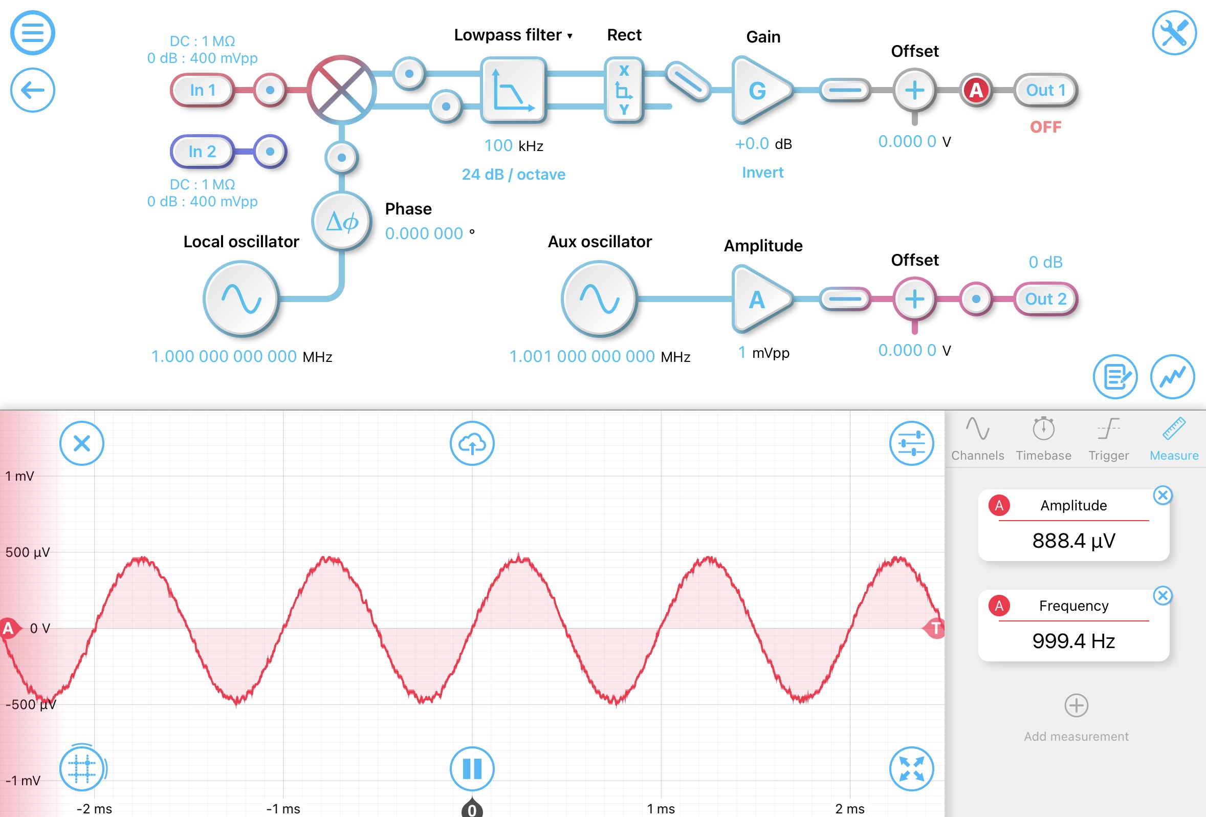
We will demonstrate the effects of different conversion ranges with the following examples. Here we generated a 1 mVpp sine wave and demodulated it with a frequency offset of 1 kHz. When we look at the the X or I component, we can measure the 1 kHz frequency and the measured amplitude is about 1 mVpp.
If we now switch to R/theta mode and use the largest 2 Vpp range to measure R, we can see the amplitude is about 500 uV. However, the measured amplitude is relatively noisy. As the signal of interest is only 1 mVpp, it will be more suitable to use a smaller conversion range.

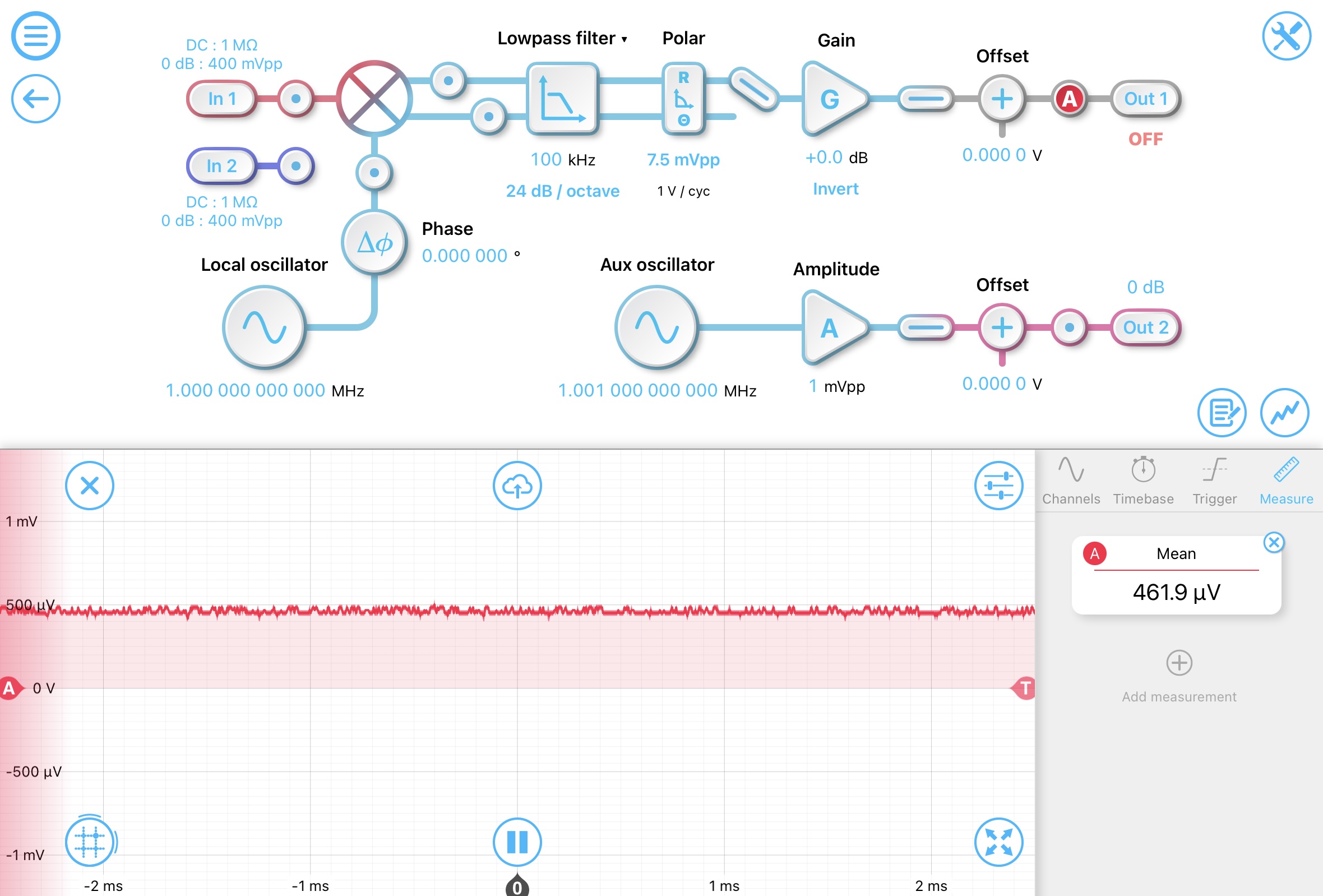
Now if we switch the conversion range down to 7.5 mVpp, we can see that the measured R is still accurate, but the output is less noisy.
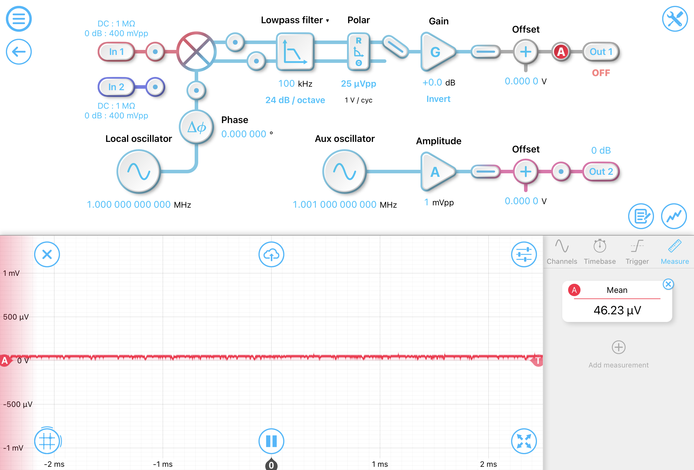
However, if we then switch to the smallest conversion range of 25 uVpp, the measured R is now inaccurate since the conversion range has been exceeded.