What if my actuator can't take negative voltages?
-
Moku:Go
Moku:Go Arbitrary Waveform Generator Moku:Go Data Logger Moku:Go Frequency Response Analyzer Moku:Go Logic Analyzer & Pattern Generator Moku:Go Oscilloscope & Voltmeter Moku:Go PID Controller Moku:Go Spectrum Analyzer Moku:Go Waveform Generator Moku:Go Power Supplies Moku:Go Digital Filter Box Moku:Go FIR Filter Builder Moku:Go Lock-in Amplifier Moku:Go General Moku:Go Logic Analyzer/Pattern Generator Moku:Go Time & Frequency Analyzer Moku:Go Laser Lock Box Moku:Go Phasemeter
-
Moku:Lab
Moku:Lab General Moku:Lab Arbitrary Waveform Generator Moku:Lab Data Logger Moku:Lab Digital Filter Box Moku:Lab FIR Filter Builder Moku:Lab Frequency Response Analyzer Moku:Lab Laser Lock Box Moku:Lab Lock-in Amplifier Moku:Lab Oscilloscope Moku:Lab Phasemeter Moku:Lab PID Controller Moku:Lab Spectrum Analyzer Moku:Lab Waveform Generator Moku:Lab Time & Frequency Analyzer Moku:Lab Logic Analyzer/Pattern Generator
-
Moku:Pro
Moku:Pro Arbitrary Waveform Generator Moku:Pro Data Logger Moku:Pro Frequency Response Analyzer Moku:Pro Oscilloscope Moku:Pro PID Controller Moku:Pro Spectrum Analyzer Moku:Pro Waveform Generator Moku:Pro Lock-in Amplifier Moku:Pro Digital Filter Box Moku:Pro FIR Filter Builder Moku:Pro Phasemeter Moku:Pro Multi-instrument Mode Moku:Pro General Moku:Pro Logic Analyzer/Pattern Generator Moku:Pro Time & Frequency Analyzer
- Python API
- MATLAB API
- Arbitrary Waveform Generator
- Data Logger
- Digital Filter Box
- FIR Filter Builder
- Frequency Response Analyzer
- Laser Lock Box
- Lock-in Amplifier
- Oscilloscope
- Phasemeter
- PID Controller
- Spectrum Analyzer
- Time & Frequency Analyzer
- Waveform Generator
- Logic Analyzer & Pattern Generator
- Multi Instrument Mode
- Moku Cloud Compile
- Moku general
- LabVIEW
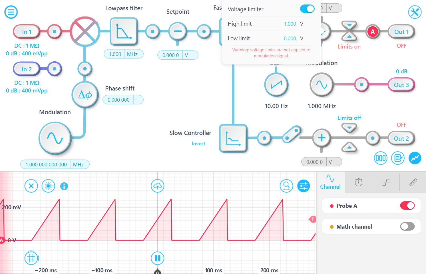
Moku Laser Lock Box has output voltage limiters designed for exactly this purpose. You can set arbitrary high and low limits on each output and the control signals will be clamped to these levels, preventing damage to sensitive actuators. For example, in the screenshot below, the limits block is configured with a high limit of 1 Volt and a low limit of 0 Volts. As a result, the output signal contains only the positive segments.
Note that the modulation signal from the auxiliary oscillator is not clamped to avoid clipping and distortion.