Lock-in Amplifier's amplitude R output meaning
Explanation of the R amplitude

Written by Heyang Long
Updated at July 23rd, 2024
-
Moku:Go
Moku:Go General Moku:Go Arbitrary Waveform Generator Moku:Go Data Logger Moku:Go Digital Filter Box Moku:Go FIR Filter Builder Moku:Go Frequency Response Analyzer Moku:Go Logic Analyzer & Pattern Generator Moku:Go Oscilloscope & Voltmeter Moku:Go PID Controller Moku:Go Spectrum Analyzer Moku:Go Waveform Generator Moku:Go Power Supplies Moku:Go Lock-in Amplifier Moku:Go Time & Frequency Analyzer Moku:Go Laser Lock Box Moku:Go Phasemeter
-
Moku:Lab
Moku:Lab General Moku:Lab Arbitrary Waveform Generator Moku:Lab Data Logger Moku:Lab Digital Filter Box Moku:Lab FIR Filter Builder Moku:Lab Frequency Response Analyzer Moku:Lab Laser Lock Box Moku:Lab Lock-in Amplifier Moku:Lab Oscilloscope Moku:Lab Phasemeter Moku:Lab PID Controller Moku:Lab Spectrum Analyzer Moku:Lab Time & Frequency Analyzer Moku:Lab Waveform Generator Moku:Lab Logic Analyzer/Pattern Generator
-
Moku:Pro
Moku:Pro General Moku:Pro Arbitrary Waveform Generator Moku:Pro Data Logger Moku:Pro Frequency Response Analyzer Moku:Pro Oscilloscope Moku:Pro PID Controller Moku:Pro Spectrum Analyzer Moku:Pro Waveform Generator Moku:Pro Lock-in Amplifier Moku:Pro Laser Lock Box Moku:Pro Digital Filter Box Moku:Pro FIR Filter Builder Moku:Pro Phasemeter Moku:Pro Multi-instrument Mode Moku:Pro Logic Analyzer/Pattern Generator Moku:Pro Time & Frequency Analyzer
- Python API
- MATLAB API
- Arbitrary Waveform Generator
- Data Logger
- Digital Filter Box
- FIR Filter Builder
- Frequency Response Analyzer
- Laser Lock Box
- Lock-in Amplifier
- Oscilloscope
- Phasemeter
- PID Controller
- Spectrum Analyzer
- Time & Frequency Analyzer
- Waveform Generator
- Logic Analyzer & Pattern Generator
- Multi Instrument Mode
- Moku Cloud Compile
- Moku general
- LabVIEW
- mokucli
The Lock-in Amplifier is a widely used instrument for small signal analysis in environments with significant noise. The Lock-in Amplifier offers several output modes, including X/Y and R/θ. However, due to the complex processing chains within the Lock-in Amplifier, there is no direct relationship between the input signal amplitudes and the R output.
In the specific case where the input signal consists of a single frequency tone, the output signal amplitude can be directly determined if the input signal is demodulated at its own frequency.
1. Single-tone input signals:
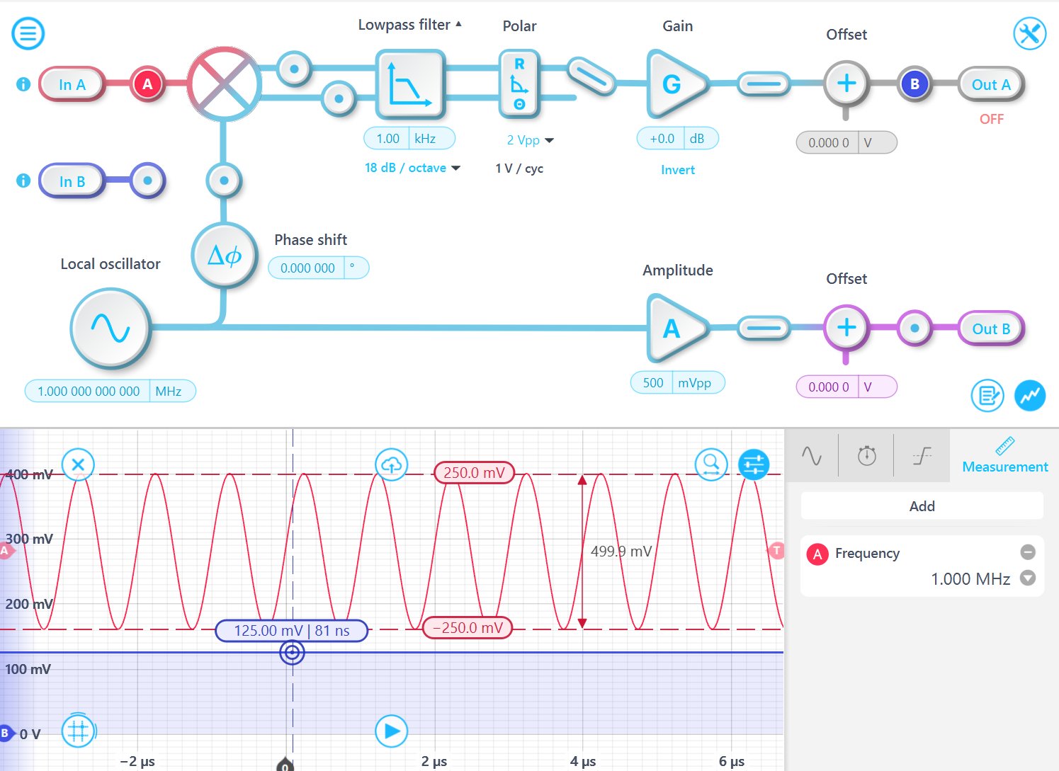
Consider an input signal of the form: Asin(ft), demodulated at the same frequency f. The output of the mixer is: Asin(ft)sin(ft). Using the double angle formulas, this signal can be expressed as: [1 - cos(2ft)]A/2. The component 2f will be filtered by the lowpass filter, leaving A/2. Thus, the output R is half of the signal amplitude A, and one-quarter of the peak-to-peak amplitude value.
Experimental results confirm this relationship: for a 1 MHz signal with a 500 mVpp amplitude signal, the demodulated results R is 125 mV.
The input signal frequency does not need to match the demodulation frequency exactly. As long as the frequency difference is smaller than the corner frequency of the low-pass filter, the mapping relationship remains valid.
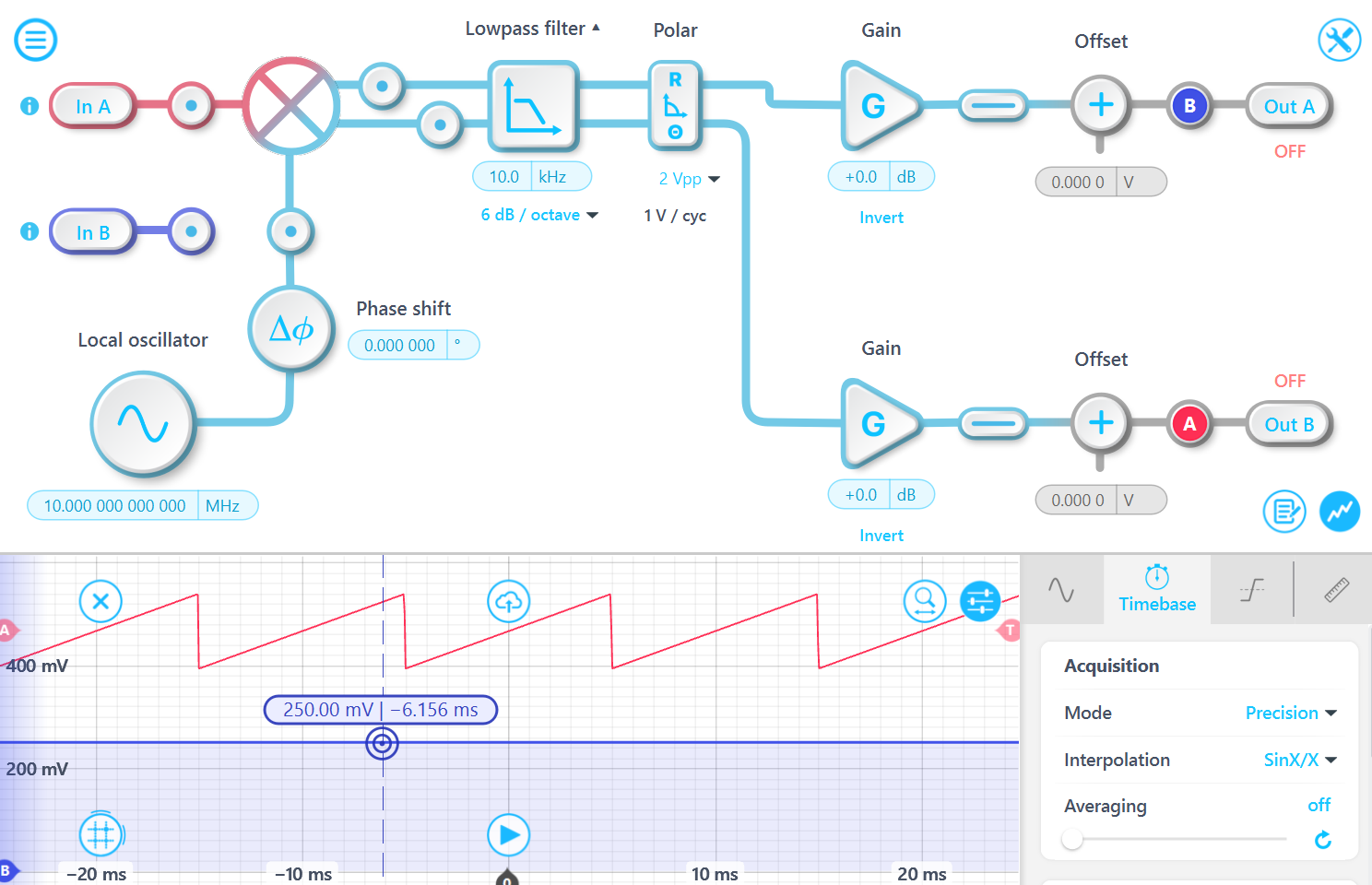
For an input signal A⋅sin(f1⋅t), demodulated at the frequency f2, the resulting signal after mixing is: A/2⋅{cos[(f1- f2)⋅t] - cos[(f1 + f2)⋅t]}. After passing through the low-pass filter, the high-frequency component is attenuated, leaving: A/2⋅cos[(f1- f2)⋅t]. Given that the Moku Lock-in Amplifier employs a dual-phase demodulator (in-phase and quadrature-phase), the computed amplitude R is sqrt({A/2⋅cos[(f1- f2)⋅t]}^2 + {A/2⋅sin[(f1- f2)⋅t]}^2) equals to A/2.
A 10.000 1 MHz signal with a 1 Vpp amplitude is demodulated using a 10 MHz demodulation signal. The output exhibits the expected amplitude and undergoes periodic phase changes at a frequency of 100 Hz.
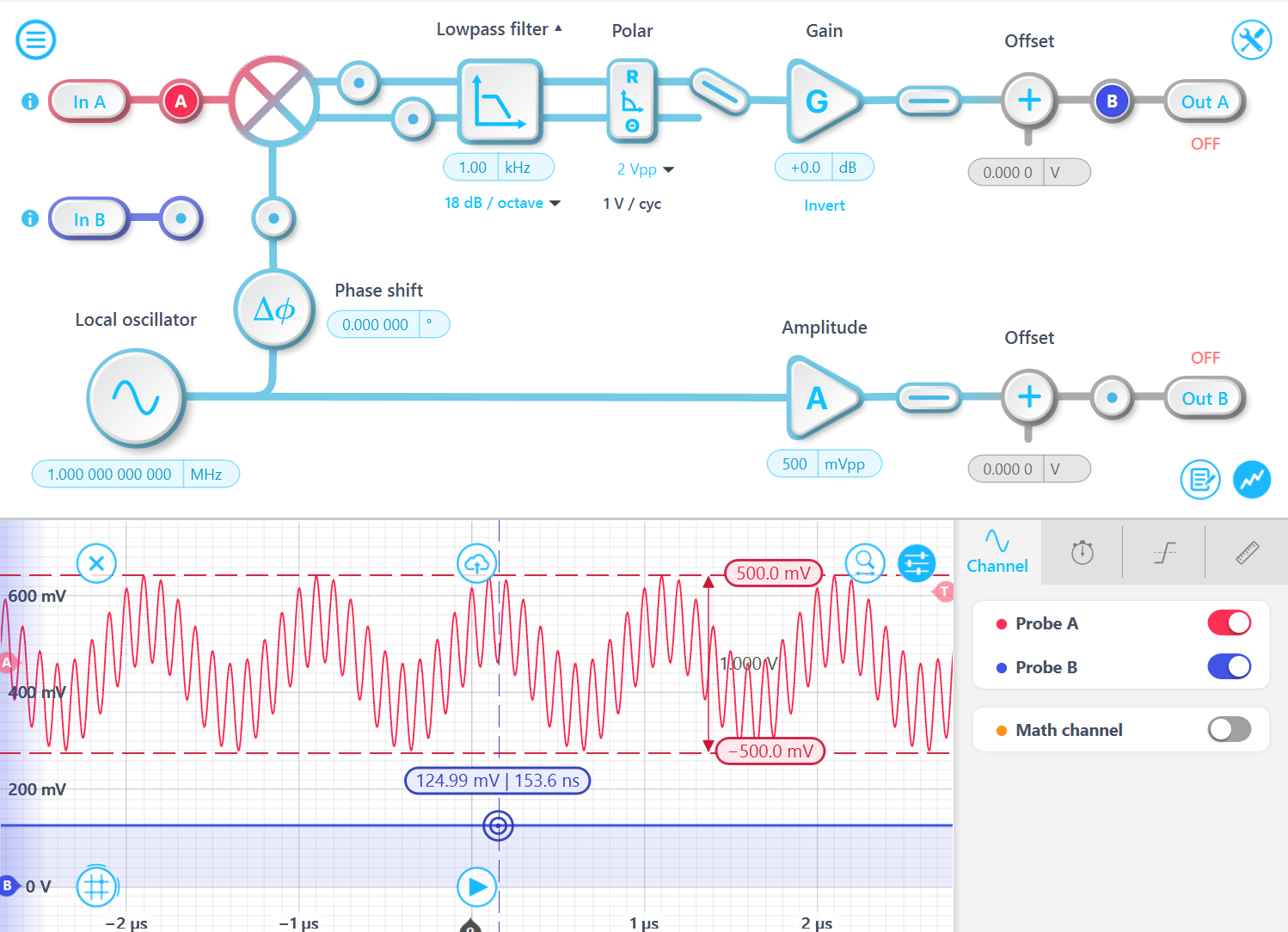
However, please note that this mapping relationship only applies to single frequency tone signals. For more complex signals, this relationship does not hold because the additional frequency components will be filtered out, resulting in signal loss and amplitude reduction.
For example, consider a test with an input signal containing two frequency tones: 10 MHz and 1 MHz. The baseline signal is a 1 MHz, 500 mVpp sine wave, with a 10 MHz, 500 mVpp signal superimposed on it. In this case, the R output amplitude remains 125 mV, even though the total input signal amplitude is now 1 Vpp. This occurs because the 10 MHz tone is filtered out by the 1 kHz bandwidth low-pass filter.
2. Amplitude modulated (AM) input signals:
For a message signal modulated on a fundamental carrier, the demodulated amplitude is expected to be A⋅d/2 of the original modulated signal, provided the message frequency is within the lowpass passband. Here, A is the amplitude of the carrier waveform, and d is the modulation depth. The modulated signal A⋅sin(f⋅t)⋅[1+d⋅sin(m⋅t)] can be expressed as (1−cos(2f⋅t))⋅A/2⋅[1+d⋅sin(m⋅t)] after demodulation, and the low-passed signal is A/2⋅[1+d⋅sin(m⋅t)].
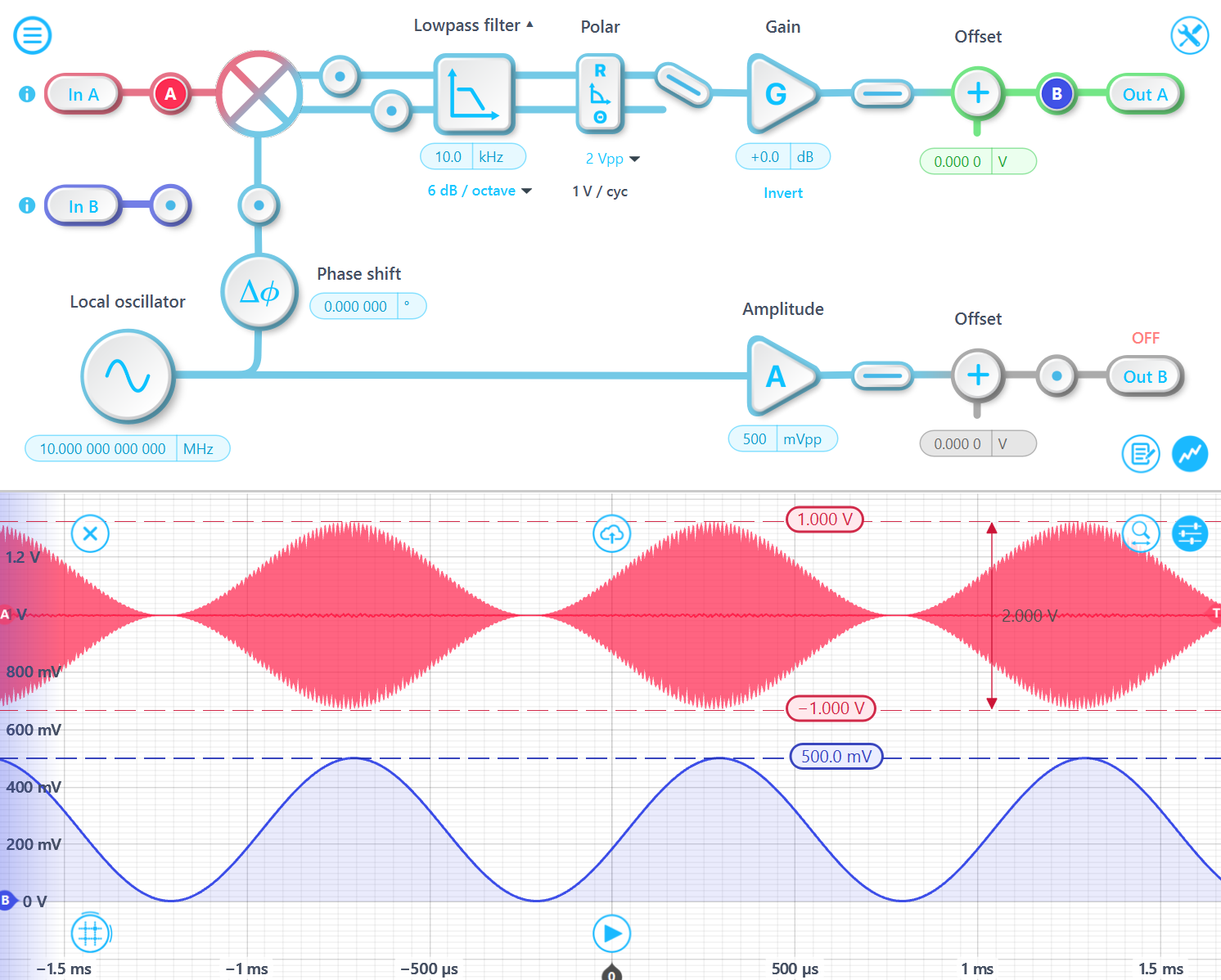
For example, consider an input signal with a 1 Vpp 10 MHz carrier wave, 100% modulated by a 1 kHz sine wave. The peak-to-peak amplitude of the input signal is 2 Vpp because the maximum value of A⋅sin(f⋅t)⋅[1+sin(m⋅t)] is 1 and the minimum value is -1. The demodulated output peak-to-peak amplitude is 500 mVpp, which is 1/2 of 1 Vpp since d is 100%.
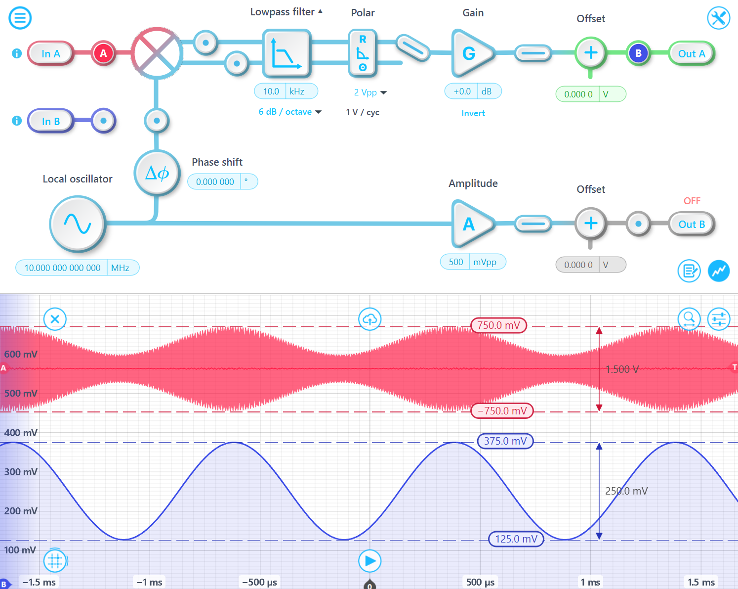
In the case where the signal is 50% modulated, the peak-to-peak amplitude of the input signal is 1.5 Vpp since the maximum value of A⋅sin(ft)⋅[1+0.5⋅sin(m⋅t)] is 0.75 and the minimum value is -0.75. Moreover, the demodulated output peak-to-peak amplitude is 250 mVpp, which is d/2 of 1 Vpp.
In summary, the input-to-output amplitude relationship follows a 1/4 mapping. However, this only applies when the signal consists of a single frequency tone. In other words, the R output represents a quarter of the peak-to-peak amplitude of the input signal component that matches the demodulation frequency. If there is a message signal on the carrier wave, the amplitude of the demodulated message signal would be A⋅d/2, where A is the carrier amplitude, and d is the modulation depth.